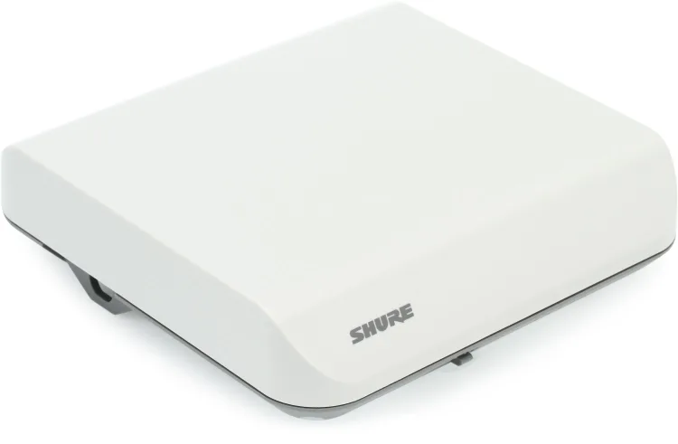
Sound system installers favor the UA864 antenna because it does not look like an “antenna” and can be painted to match the interior of the room. However, the UA864 is often misapplied. Here are seven practical hints regarding this “doppelganger for a smoke detector.”
Hint #1: The UA864-US, for example, is a wide-band antenna, i.e., it covers 470-698 MHz. A wide-band antenna is best used when the installed wireless system employs the entire “wide-band” of 470-698 MHz. If the wireless system operates over a restricted range, say 516-542 MHz, it is better to use ½ wave antennas design to cover just this range. Why? Because a wide-band antenna captures frequencies outside of the “area of interest” and relies upon the front-end filters of the receiver to ignore these unwanted frequencies. Better to choose an antenna that is band-limited and “listens” only to the frequencies of interest.
Hint #2: The UA864 has a gain switch with settings of -20, -10, 0, and +10 dB. During installation, set the gain to 0 dB. If the system works are desired, leave the switch at 0 dB. Do not increase the gain if the receiver RF signal levels are satisfactory.
The +10 dB setting is required only when the UA864 is connected to a long antenna cable run. An RF signal is diminished as it travels down a cable; the exact level of signal reduction (attenuation) per foot depends upon the type of cable. If the cable attenuates the signal by 10 dB to 16 dB, the gain switch is set to +10 dB to compensate for the signal loss in the cable.
INCREASED GAIN DOES NOT IMPROVE ANTENNA PERFORMANCE. It merely offsets the signal loss which occurs within the antenna cable.
The -10 dB setting or -20 dB setting is selected if the UA864 RF Overload LED illuminates. Start with -10 dB. Move to -20 dB only if the RF Overload LED remains lit.
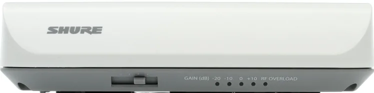
Hint #3: The UA864 does not require 12 Vdc bias with gain settings of -20, -10, and 0. The 12Vdc bias is only required for the +10 dB gain setting and to activate the LED indicators on the side of UA864.
Hint #4: The UA864 is polarized. With the gain switch facing the ceiling, the UA864 is vertically polarized. With the gain switch facing a wall, the UA864 is horizontally polarized. For most installations, position one antenna vertically and the other horizontally. If boundary microphone transmitters are the only transmitters used, position each UA864 unit horizontally.
Hint #5: Once positioning is determined, based on polarization and line-of-sight, and the UA864 units are secured to a mounting surface, the covers can be detached and rotated in any direction for a matched appearance.
Hint #6: Yes, the wireless mic system does indeed require two UA864 antennas. Suggested spacing is a minimum of 48 inches with clear line-of-sight to each transmitter in use.
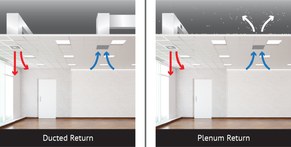
Hint #7: The UA864 is not plenum-rated. (See Arcana below for the definition of a plenum.) Installing the UA864 in a plenum space violates Fire and Safety codes. Why? If the plastic case of the UA864 melts during a fire, toxic fumes are created within the plenum space. Air movement within the plenum spreads toxic fumes to other rooms.
Related links: Antenna Setups for Wireless Microphones
Arcana – mysterious or specialized knowledge
Plenum: a space, usually above a suspended ceiling, that serves as a receiving chamber for air that has been heated/cooled to be distributed into inhabited areas. From the Latin, plenus, meaning “full.”
***
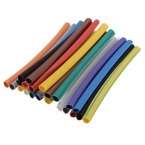
Need to the change the color of a ½ wave whip antenna? Don’t paint it. Cover it with heat-shrink tubing, available in many colors.
***
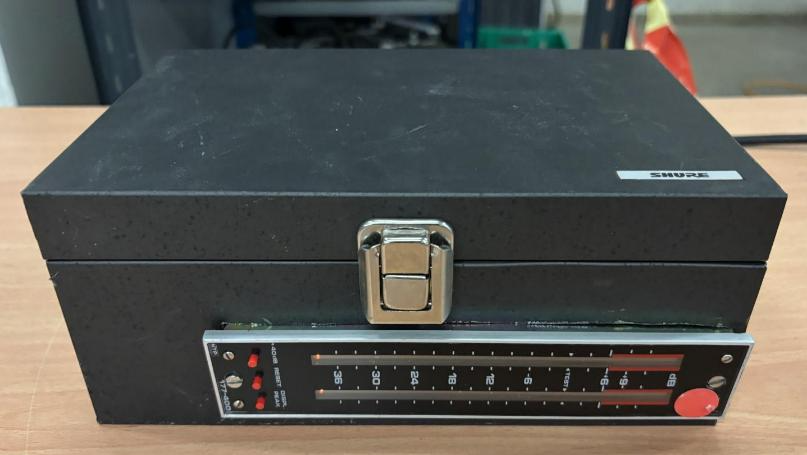
Tech Tip reader Topi Suuronen, based in Finland, provided the following photo of a “rare” Shure product being sold that turned out to be unique but not valuable. It is a VU meter mounted in a Shure metal storage box once supplied with our SM7 microphone. Engineers in Suomi have an unusual sense of humor…could be the months of winter darkness.