
If one is new to the professional audio industry, the term “phantom power” can be confusing. So first, a primer: What Is Phantom Power?

1930s Car of Tomorrow
Now the history…
Decades before phantom powering was developed for condenser microphones there was a similar concept, called “simplex,” employed for telephone systems. The definition of telephony simplex is:
A circuit in which a ground-return telephone is superimposed on a full metallic circuit to obtain an extra communication channel. Provision is made to prevent interaction or interference between the two communication channels.
How does this arcane definition apply to modern phantom power? The “full metallic circuit” (XLR pin 2 and XLR pin 3) is the balanced path for the AC (alternating current) microphone signal. The “ground-return” circuit (XLR pin 2, XLR pin 3, and XLR pin 1) is the path for the DC (direct current) phantom power.
Once again, Bell Labs research underlies a technical standard used in professional audio. Telephony simplex laid the foundation for phantom power. A Visit to Bell Labs
An early phantom powered microphone was the Schoeps CMT 20 from 1964. Designed to French Radio specifications, the mic required 9 to 12 Vdc (Volts direct current) of phantom power. The positive voltage side of this powering scheme was grounded…highly unusual. Microphone preamplifiers in Swiss-made Nagra IV tape recorders offered this early form of phantom power as an option. Schoeps supported “Negative Phantom” until the CMT microphone series was discontinued in the 1970s. Thankfully, this embryonic form of phantom power is now obsolete.

In 1966, Neumann proposed a new transistorized microphone to NRK, the Norwegian Broadcasting Corporation. The radio branch of NRK requested phantom power operation for this mic. As NRK had 48 Vdc available in their studios for emergency lighting systems, this voltage was a convenient source for powering the newly developed KM 84 mic. Thus, the origin of 48 Vdc phantom power, now formalized as DIN standard #45 596, can be allegedly traced to emergency lighting in Norway.
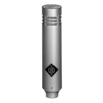
Today, international standard IEC 61938 delineates phantom power. Two inner conductors of the mic cable carry the positive DC voltage, fed through a center-tapped input transformer or through matched precision resistors. For 48 Vdc phantom power, the resistor value is 6,800 ohms. The cable shield is the return path (ground) for the positive phantom voltage.
It is worth noting that carbon microphones, widely used in the early 20th century, required up to 50 Vdc for operation, and, like phantom, had an AC signal and a DC signal flowing on the same wires. In addition to telephony simplex, the carbon mic circuit inspired the development of phantom power for condenser microphones.
Related information: Phantom Power and Cable Length
Will Phantom Power Damage a Wireless Mic Receiver?
Arcana – mysterious or specialized knowledge
What is the meaning of the Neumann “KM” prefix?
KM stands for kleines Mikrofon – small microphone – natürlich!
***
Shure adopted a similar nomenclature for the Unidyne II Model 55S where “S” = “Small.”
Compared to the Unidyne I, the Unidyne II is 33% smaller.


I love it – Thank you!
Thank you, nice article